


Some more pictures :
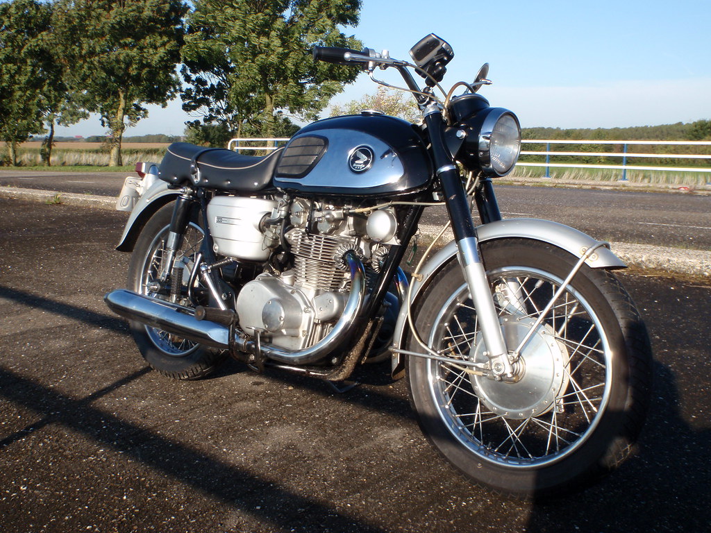
somewhere on the road by dream1964, on Flickr
and :
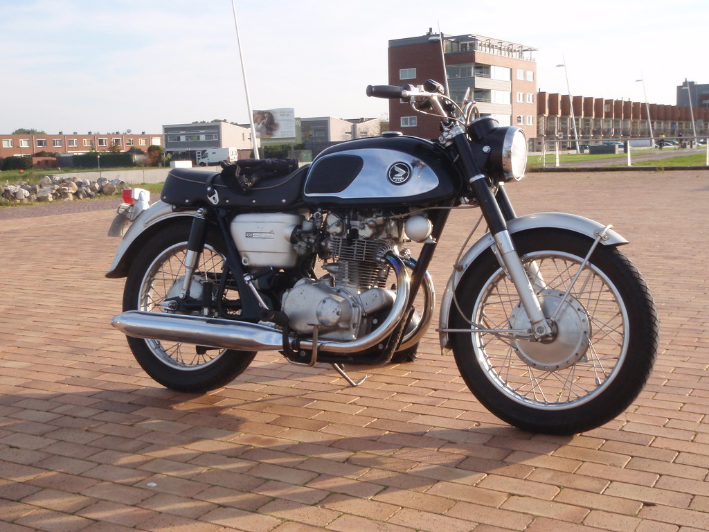
PA030109 by dream1964, on Flickr
Jensen
CB450 K0 dynojet and why it doesn't need a five speed trans
Hi,
Some more pictures : somewhere on the road by dream1964, on Flickr and : PA030109 by dream1964, on Flickr Jensen
Last edited by jensen on Wed Sep 28, 2011 3:30 am, edited 1 time in total.
assembly of Japanese motorcycles requires great peace of mind (Pirsig)
Hi,
For anyone who is interested in this thread, I wen't further and deeper in this stuff at the hondatwins forum. Find it here : http://www.hondatwins.net/forum/viewtop ... =56&t=5033 I think you have to register because otherwise pictures cannot be seen. Jensen assembly of Japanese motorcycles requires great peace of mind (Pirsig)
Hi,
In an article of the CB 450 K1, there was an interesting dyno curve (thanks Wiemer). I gave it the same dimensions as my own curves and guess what ?, they don't differ that much. Later I will explain the details, but for now the curves. For those who aren't able to see the curves and illustrations on the link, I placed them here. Jensen
assembly of Japanese motorcycles requires great peace of mind (Pirsig)
I’ll try to explain what is seen in both graphs (from this point I’ll use only the curve “ratio” and my own curve.).
We should be aware, that my curve is from a CB450 K0, the curve from the article is from a CB450 K1. In the literature the K1 has a higher output then the K0, 1 Hp (If I take the K0 as a reverence, the K1 has 2,3% more power). The first thing what attract the eye is that the curves given in the article are starting at 4000 rpm, and that makes it impossible to compare the max torque peak what is so typical for the curve of my standard K0 This has everything to do how they measured in the those days (1968). So, how did they measure the curves as showed in the article ? I will try to explain. First of all the article shows three curves, the curves are drawn by hand (also the scales and the comments), and in Dutch, so first I will translate. Honda CB450 5 versnellingen = Honda CB450 five speed Then the name of the curves : Krukasvermogen (SAE) = crank output power (SAE) Achterwielvermogen (DIN) = Rear wheel output power (DIN) Moment = Torque And finally the scales : PK = HP Tpm = rpm kgm = kgm The relation between KGM (kilogram metre) and Nm (Newton meter) is the gravitational acceleration, and is 9,81, so 1 kgm is 9,81 Nm. In the article three curves are given, but only one is actual measured, and that is the rear wheel power output curve. The crank output and Torques curves are mathematical derived from the measured crank output power curve. So how exactly did they measure the rear wheel output power curve in 1968 ? The curve is measured at the TU- delft (Technical university in Delft), and I happen to know that in 1968 they “dyno” was an Eddy current brake device. So how does it work ? The Eddey current brake is driven by the rear wheel of the bike. The bike has to deliver power to overcome the braking power of the device. The braking power is controlled and measured, and is directly related to the rear wheel output. So why not measure the power output below 4000 rpm ? I’ll try to explain as well : When looking close to the curve it is shown that the curve is drown by hand, as an interpolation around points. One point is a relation between Power and rpm. Every point is a measurement, so if you measure power at 6000 rpm, at 7000 rpm and at 8000 rpm, you will have 3 points, and now you can interpolate a line between those points, now a curve is shown. I don’t know how many points are used in the curve, but measuring one point was a difficult task, so a curve consisting from a lot of points is a very time consuming job. So they were kind of lazy below the 4000 rpm ? No, it was just not possible to extract measurements below 4000 rpm without risking severe damage on the engine. Why ? Because of the way the power was measured. Visualize a motorcycle, with it’s rear wheel on a big drum, which holds the Eddy current brake. You start the engine and let it rev to for example 6000 rpm. As in the beginning, the eddy current brake isn’t activated, so there is virtually no load. While keeping the engine revving at 6000 rpm, you activate the Eddy current brake a bit (increasing the load), to the point that the bike starts decrease in rpm. To compensate this you automatically open the throttle a bit, the rpm increases again until it hits the 6000 rpm again. Now you brake a little harder (increasing the load), a decrease of the rpm will follow, you open the throttle a bit more, etc. At a certain moment the system will be in balance, that means that the engine is delivering a max power at 6000 rpm, without increasing or decreasing the rpm, while the eddy current brake is at it’s maximum braking power (load) for that rpm. Now you have determined how much power the engine can deliver at a certain rpm 6000 rpm in this example) without accelerating or decelerating while pulling a maximum load at that rpm. For every given point in the rpm range you have to do the same measurement until you have enough points to draw a curve. If you want to measure this balance point between max load and max output power at for example 2000 rpm, the engine wouldn’t be happy at all, and severe engine damage is possible, or actually likely. Now you know how they did it, and we can start comparing the curves. Jensen assembly of Japanese motorcycles requires great peace of mind (Pirsig)
| |||||||||||||||||||||||||||||||||||||||||||||||||||||||||||||||||||||
