Electronic Ignition - CB72, CB77, CP77, CL72, CL77 |
Genesis and Beyond
(or how the e-Ignition for Vintage Hondas came to be)
 |
For a complete picture, take a look at the other pertinent sections:
The genesis of the Superhawk electronic ignition system began, oddly enough, with the purchase of someone else’s mothballed 1976 Yamaha XS-650 twin some time in 1995. Like many of you out there, I have this motorcycle disease, which makes me want to "rescue" old non-runners and get them back on the road. My particular weaknesses run to machines from the 1970s, for what I suppose are the usual reasons – lost youth, "wanted-it-but-didn’t-have-the-money" syndrome, and so forth. Since the XS-650 was a typical 70s bike, it was complete with dual, camshaft-driven breaker points, centrifugal spark advance, and notoriously weak ignition coils. The ignition system was purported to be the weakest link in getting really good street performance from these bikes, according to contemporary hop-up articles I’d located before making the purchase.
Besides the usual hassles of weak coils, faulty condensers, rubbing-block grease on the contacts, incorrect dwell settings, contact misalignment and pitting, and so on, I found other problems. This, otherwise clean and sound example, had a centrifugal advance mechanism that was really tattered and worn out. In particular, the two little "dogs" that extend from the flying weights to engage and rotate the points cam about its axis were ground down from lack of lubrication, and the whole mechanism was simultaneously sloppy and half-seized, if you can imagine such a combination.
Looking at this mess put me in mind of the first time I had taken an engine completely to bits and put it back together, that of my first "big" bike, a well-used 1965 CB77 Superhawk. (For those with Superhawk experience, my bike had the common "jumps-out-of-second-gear" problem, and I had to split the cases to install the offset second-gear cotter that was needed to fix it.) The Superhawk, of course, has its centrifugal advance mechanism located inside the engine, on the built-up cam-drive sprocket, right in the middle of the camshaft assembly. For this reason, it would be unusual to find a Superhawk advancer that’s been starved of lubrication. (The return springs do break off and fall down into the sump, however, as I found one of mine had done when I got the top end apart – I had been wondering why I couldn’t get it to idle smoothly.) In any case, the "dry" Yamaha system was in bad shape, and I had decided that I wanted to upgrade to a no-points, all-electronic ignition system, if I could.
One way to carry out the upgrade was a graft from the bike boneyard – Yamaha fitted pointless transistorized ignitions as standard to the XS-650 models from 1980 onwards. The retrofit involved obtaining the alternator rotor and stator from the later model (the rotor carried the trigger magnet, and the stator housing carried the pickup). These turned out to be a little pricey and hard to find. Rotor windings are well-known failure points on these bikes, and the ignition pickups are notorious too – so a lot of the bikes in the boneyard are there because these parts failed, and someone decided it was uneconomic to fix them. A second problem, if I did find the 1980-and-onwards parts in good shape, was the relatively unsophisticated electronic spark advance curve of these early OEM parts, which I felt would not yield a top-notch runner in any case.
The alternative of an aftermarket all-electronic ignition system ("all-electronic" meaning with an electronically-controlled advance curve, as well as pointless triggering) seemed not to be available. At that point, I decided to design and build exactly what I wanted. (Much later, I ran across a system for the XS-650 adapted from an English aftermarket product, but its performance was not what I was looking for, as it turned out.)
Not too long after I got the first couple of prototype ignitions running on the ’76 bike and its ’79 stablemate (acquired to serve as a second test mule), I had the very good fortune to make the acquaintance of Mr. Bill Silver. He and his Superhawk were parked at the Lookout Roadhouse on Ortega Highway, a motorcycle-friendly local canyon road. I walked up and introduced myself, gave Bill an "I-used-to-own-one-of-those" story, and offered to build him an electronic ignition system in exchange for using his bike as a starting point for the design work. Bill agreed, and after a while I went over to visit him and take measurements off of his machine. Bill also loaned me a spare cylinder head, complete with camshaft plus points housing and cover, and we were on our way.
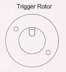
About the first thing I found out, because Bill was knowledgeable enough and persistent enough to educate me, was that adapting my existing ignition system, with built-in electronic advance, to the Superhawk was a little bit futile, for two reasons. First, most Superhawk owners were not going to be willing to drop the motor and pull off the camshaft cover, then go in and disable the centrifugal advance mechanism, then put it all back together again, just to see how they liked this new ignition system. Second, there was no simple and obvious way to mechanically pick up the "fixed" part of the hollow right-side camshaft half itself – it being largely buried behind the points housing. (The significance here is that the trigger rotor on an electronically-advanced system has to be fixed in angle relative to the camshaft, so the rotor can’t mount to the existing points cam unless the advance mechanism is "locked".) Against all my previous experience of designing the more-complex electronically-advanced ignition, the best solution for the Superhawk seemed to be to retain the original centrifugal advance and add pointless switching. So, we all have Bill to thank for getting me past my engineering myopia on this point.
Getting to the final system was a three-part job. First, I designed up and had machined a prototype of the small aluminum rotor that mounts over the existing points cam and carries the magnets that trigger (and un-trigger – the spacing between these two events determines the dwell angle) the Hall-Effect sensors that signal when it’s time to spark. At the same time, I designed and had fabricated the fiberglass-backed printed-circuit board (PCB) that replaces the original points backing plate and carries the Hall-Effect sensors. Finally, I hand-build a control box containing the power transistors that actually turn the coil current on and off, using point-to-point wiring inside a commercial die-cast housing. We went through a little fiddling with this setup and got it working, and Bill proceeded to put some test miles on the bike.
Next, I designed and built a batch of printed-circuit boards to replace the hand-wired control box. Again, after a little more fiddling, we had this version working. This first PCB used through-hole parts (the kind of electronic parts that have wire leads on them that you poke through the solder-plated holes of the PCB, and then solder them in place). At about 3" by 2.5" by 1" thick, the PCB version was roughly 2/3 the size of the hand-wired prototype, and I thought I was happy – for a while.
While the Superhawk system was evolving, the XS-650 ignition system grew up to be pretty complicated, and while it worked just like I wanted it to, I was unhappy about its size, about 6" by 3" by 1" deep. While that’s no worse than a lot of OEM "black boxes," it’s still always hard to find somewhere on (or in) a motorcycle chassis to mount a clunky rectangular thing with a connector and wires coming out of it. After chewing this problem over for a while, I decided to bite the bullet, and redesigned the whole circuit to use surface-mount electronic parts. These parts are really tiny – half the size of their conventional wire-leaded, through-hole counterparts. The redesign effort resulted in an acceptably tidy package for the XS-650 ignition – but now the Superhawk ignition’s control box looked kind of bulky in comparison.
The last step in the Superhawk ignition saga was to use the same surface-mount technology to design a brand-new, smaller control-box PCB for the Superhawk that could be mounted into a really tiny box and potted with epoxy to make it water-resistant and vibration-proof. This last change resulted in a control box 2.3" by 1.7" by 0.9", including a finned aluminum heat-sink to assist in cooling the smaller, tighter package. At this size and weight, there are a lot more inviting places to mount the box, as illustrated in Michael Stoic’s nearby chronicle of the installation he performed on his own bike.
For a little technical detail, here’s how the system works in general terms:
The two Hall-Effect sensors, one for the left-hand cylinder and one for the right-hand cylinder, are mounted on the pickup plate PCB that fits where the points backing plate originally mounted. Like the points backing plate, the pickup plate’s mounting holes are slotted to allow rotation for ignition timing adjustment. The two sensors are located exactly 90� apart in angle, which of course equates to 180� of crankshaft rotation between the two firing events (for the CB/CL Type 1 engines). The Hall-Effect sensors don’t fire the ignition coils directly – they can only handle a few milliamperes of current, and the coils draw a few amperes. Instead, the Hall-Effect sensors send a signal to the control box, which houses a pair of independent high-voltage power transistors, one for each cylinder. These transistors switch the coil current, under the timing direction of the Hall-Effect sensors. The transistors are rated to handle the inductive kick-back created by the coils when they fire. This is the same kick-back that would ruin mechanical contact points very quickly with arcing if the condensers (capacitors) of the original setup were not there to absorb the energy. Leaving the condensers out of the circuit when rugged modern transistors are employed helps make a stronger spark, since the condensers are not there to rob a little of the spark energy each time the plug fires.
The rotor on the end of the camshaft carries two magnets, located 180� apart on the rotor. One magnet causes the Hall-Effect sensor to "tell" its corresponding power transistor to cut off the coil current, causing the magnetic field in the coil to collapse and inducing a high-voltage surge in the secondary winding, creating a spark at the plug. The second magnet tells the Hall-Effect sensor to start the current flowing through the coil again, building the magnetic field in the coil back up and preparing it to create the next spark. The "dwell" angle is the amount of crankshaft rotation (in degrees of angle) during which coil current is flowing. Since it takes a while for the magnetic field in the coil to build up to its maximum level ("coil saturation"), a good goal is to have the dwell angle occupy enough time to fully saturate the coil, even at high engine speeds. With the rotor magnets situated at 180� on the cam, the crank rotation during dwell is 360� for each cylinder. Even wound up to 12,000 RPM ("Kids, don’t try this at home, this is for professional racers on a closed course……"), a 360� (at the crankshaft) dwell angle corresponds to 5 milliseconds, which is long enough for most all ignition coils to reach over 90% of their maximum energy storage. This dwell time is substantially longer than that delivered by the mechanical breaker-points setup. Especially in the upper 2/3 of the rev range, the longer dwell and resulting higher spark energy is responsible for snappier engine performance, even with stock coils.
For those interested in ultimate performance, the solid-state ignition system is designed to handle high-energy aftermarket coils, down to about 3 ohms of primary resistance. 3-ohm coils shouldn’t be used with breaker points, because the higher primary current fries the contacts in short order - a 4.5 to 5 ohm coil is the common lower limit for a points system. While the difference may not seem large, a 3-ohm coil draws 50% more current, all things being equal, than a 4.5-ohm coil, and more current generally equates to more spark energy.
***
That’s the story behind the Superhawk ignition system. For installation details and other pertinent information, follow the links below...
|
| CB-77 | CYP-77 | Road Test | Riding Log | Literature | Zen | Marketplace | VJ Survey | Links | Home |