Page 42 of 167

Posted: Wed Mar 18, 2015 12:09 pm
by G-Man
Tim / Jensen

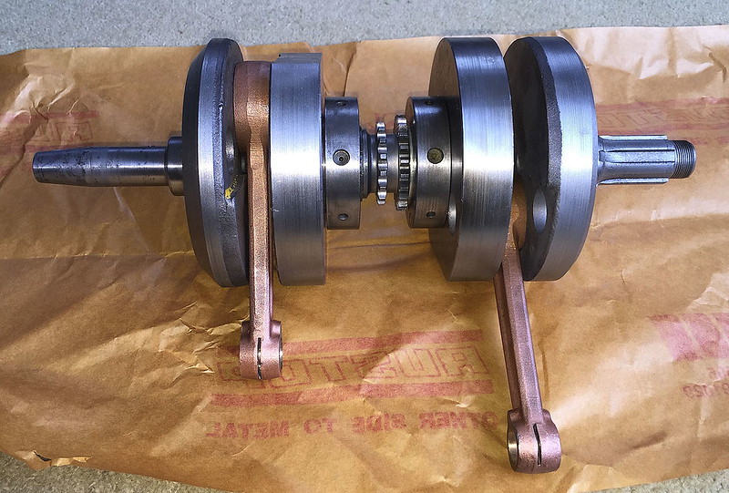
I'm wondering if this issue has something to do with the copper plating on the rods? It could be making the steel a sacrificial part, corrosion-wise. The opposite of zinc galvanic protection. My big end pins look a lot better than the inside of the rod on the same bearing.....

Rolling contact fatigue happens when cracks grow faster than the surface wear rate rubs them away and then lubricant is forced into the cracks eventually causing bits to fall away from the surface. I have seen rods that have suffered from this. http://www2.mae.ufl.edu/arakere/docs/RCF_JOT.pdf

Mild corrosion is less of a problem, I think. I have read a lot of stuff on rolling contact fatigue in railroad rails. Not exactly motorcycle crankshafts but the science is similar..... :-)

G
Tim Miller wrote:
Rust pitting is a problem I have witnessed as well. It took about 30 dismantled cranks to have enough good parts for 10 cranks. Rods and cages were scrapped the most.

Tim

Posted: Wed Mar 18, 2015 3:45 pm
by jerry
Dear G Man, Copper plating was used extensively at one time as part of heat treatment. In the case of the Honda conrods and inner flywheels made of case hardening steel the areas that are copper plated are protected during the carburizing process and therefore end up being tough and not brittle during the final case hardening and core refining. All the best Jerry

Posted: Wed Mar 18, 2015 5:20 pm
by G-Man
Jerry

Thanks for that. It was the galvanic action of the copper plate on the steel parts promoting rusting that interested me.

G
jerry wrote:Dear G Man, Copper plating was used extensively at one time as part of heat treatment. In the case of the Honda conrods and inner flywheels made of case hardening steel the areas that are copper plated are protected during the carburizing process and therefore end up being tough and not brittle during the final case hardening and core refining. All the best Jerry

Posted: Thu Mar 19, 2015 2:02 pm
by G-Man
Impatience got the better of me this afternoon so I sneaked out to the workshop to get my crank parts in the press. There was a bit of fiddling to do with spacers and I had to cut down my two alignment bars to get some clearance.

The bearing rollers went in to the mains and the pieces were lined up in the fixture and the sprocket alignment tool added to keep the pin aligned at TDC.

Image

It was then that I realized the need for something to retain the lower bearing, so a pice of bronze welding rod was pressed into service as a spring retainer.

Image


The time for dithering was over so I started pressing on the two flywheels. This proved surprisingly smooth after the excitement of pushing the crank apart. It is due to the fact that when they are being pushed back together the force increases as the crank goes back together. That compares with the rather unstable situation when you are pulling the parts apart. Lots of force is needed to get this moving then as the engagement reduces the force rapidly reduces and the parts fly apart. With my new stiffer press the process was very controllable.

Soon, it was time to remove the sprocket alignment piece and press the parts up tight to the centre shaft.

Image

As the pieces went together the force went up from a steady 5 tons up to a sold 10 signifying that the wheels were butted up tight.

Image

Time to get bearings in to the rods ready.

Image

And then get the rod on the big end pin. This new rollers made a nice snug fit on the pin.

Image

The outer wheels were pressed on a very small amount just to get the seated and then a rough alignment was made of the two wheels with a straight edge. Before I stripped the crank, I skimmed a little metal off the wheels in the lathe to make sure the wheels were all the same diameter. This really helped when getting this rough re-alignment.

Image

The outer flywheels went on very smoothly with less force than the centre section. I was able to control the 'push' right up to the last few thousandths, without anything other than gentle pressure on the pump lever. I really like my new press....

Image

And very soon it was all done. After a couple of weeks of measuring, designing jigs and machining it was almost an anti-climax. I got over that feeling when I held the crank and just felt how nice it was compared with what I started with. :-)

Image[

I still have to do the final truing up and will make up some vee-blocks to do that. That job may have to wait until I get back from my next trip.

Image

G

Posted: Thu Mar 19, 2015 2:08 pm
by R100
That looks like it was just delivered by Mr. Honda himself.

Posted: Thu Mar 19, 2015 2:11 pm
by G-Man
:-)

G

Posted: Thu Mar 19, 2015 2:54 pm
by Tim Miller
G,

Did you check the accuracy of indexed center section before pressing rod side on?
I was curious of how well your 2 post fixture keep that alignment.

Tim