Page 61 of 142

Posted: Sun Aug 18, 2013 4:20 pm
by sarals
malcolmgb wrote:Shouldn't the unit be bolted to something to aid the heatsink? Velcro will not do that.
Great point! However, the whole Podtronics module is a heatsink. I'm sure bolting it to something metal will help cooling, but it is very robustly heatsunk as it is. As a point, the instructions for the electronic ignition system I have for the bike suggest using sticky tape (it's included) to mount the control module. I assume it gets pretty warm, too. But, like the Podtronics, it's very well heatsunk.

Posted: Tue Aug 20, 2013 11:00 pm
by sarals
The Pod is installed. I used an aluminum L bracket. I wired it in using bullet connectors. The instructions say to hard wire it to the dynamo for the best performance, but I decided not to do that.

I also installed a lot of odds and ends, and spent a lot of time planning how I was going to do things. I'm also sorting out hardware. Thank heavens for the parts manual!

Image

Posted: Wed Aug 21, 2013 6:31 am
by LOUD MOUSE
Looks good and it's out of the way. ...........lm
sarals wrote:The Pod is installed. I used an aluminum L bracket. I wired it in using bullet connectors. The instructions say to hard wire it to the dynamo for the best performance, but I decided not to do that.

I also installed a lot of odds and ends, and spent a lot of time planning how I was going to do things. I'm also sorting out hardware. Thank heavens for the parts manual!

Image

Image

Posted: Wed Aug 21, 2013 8:44 am
by G-Man
Sara

Is it just too wide to face the other way so that it fits inside the rectifier bracket? That's what I was going to try and do with mine. Good idea to mount it vertically like that to get the natural convection going. I made up my own unit for an old BSA Bantam and mounted on a big alloy plate under the tank so that it was invisible with the tank on.

Nothing fancy about those units - they are just a Zener diode and full bridge rectifier in a nice single package.

Image
Rectifier by graham.curtis, on Flickr

Image
Zener Diode by graham.curtis, on Flickr

Image
'Comp' Bantam replica by graham.curtis, on Flickr

G

Posted: Wed Aug 21, 2013 8:46 am
by G-Man
Sara

Is it just too wide to face the other way so that it fits inside the rectifier bracket? That's what I was going to try and do with mine. Good idea to mount it vertically like that to get the natural convection going. I made up my own unit for an old BSA Bantam and mounted on a big alloy plate under the tank so that it was invisible with the tank on.

Nothing fancy about those units - they are just a Zener diode and full bridge rectifier in a nice single package.

Image
Rectifier by graham.curtis, on Flickr

Image
Zener Diode by graham.curtis, on Flickr

Image
'Comp' Bantam replica by graham.curtis, on Flickr

G

Posted: Wed Aug 21, 2013 8:52 am
by sarals
LM -= thank you! Thank you for the talk - I'm, sorry we cut off, too. I'll call again tomorrow, or I'll try to.

Graham, no, it doesn't fit between the tangs. I was thinking as you are! If you spread the tangs it will go in there, but there are indentations on the tangs that keep the Pod from going in all the way. The way I did mount it worked out well. There's almost a 3/8 inch between it and the battery, it's solidly mounted, and there is room behind it to tuck the wires. Yes, it will cool well. It looks okay, too!

Posted: Fri Aug 30, 2013 11:16 am
by sarals
Well, after a week "vacation", which included my last bicycle race of the season (I won!), I was able to get back to the Old Girl yesterday. I did some more painting, some more minor assembly, hunted for more parts (I need a hose for that breather on the top of the head), and pretty much finalized the installation of the electronic ignition.

I decided to mount the control unit of the ignition on the frame box section behind the engine. It will get the required airflow there, and it's mounted horizontally, as the instructions stipulate. If I need to move it, my next location would be the cavity in front of the battery. I'd have to fabricate a mount of some sort, but I can do that. Lastly, I could put it on the back of the horn, but that location causes a bit of a rat's nest with wiring. The trigger wires from the cam plate are in a braided sleeve, and they are long. If the controller was mounted on the horn, that trigger cable would have to be tucked out of the way near the coils somehow, and there it stands the possibility of picking up impulses from the coils, which the instructions say to avoid. So - the horn is the absolute last place I'd want to place the controller.

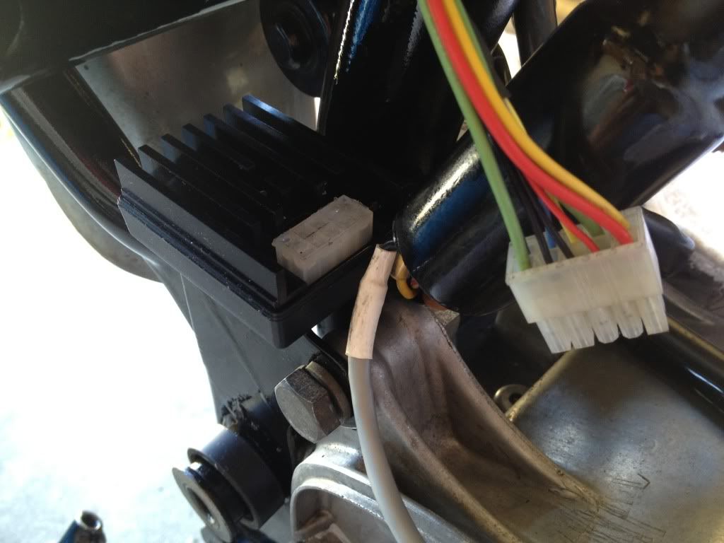
In the first photo you can see where I decided the place the controller. It's not mounted yet, it's just sitting there. There is more room for it than appears in the photo. I placed various final assembly items around it to make sure there was clearance, and there is - unless I missed something! The box will be attached to the frame with velcro.

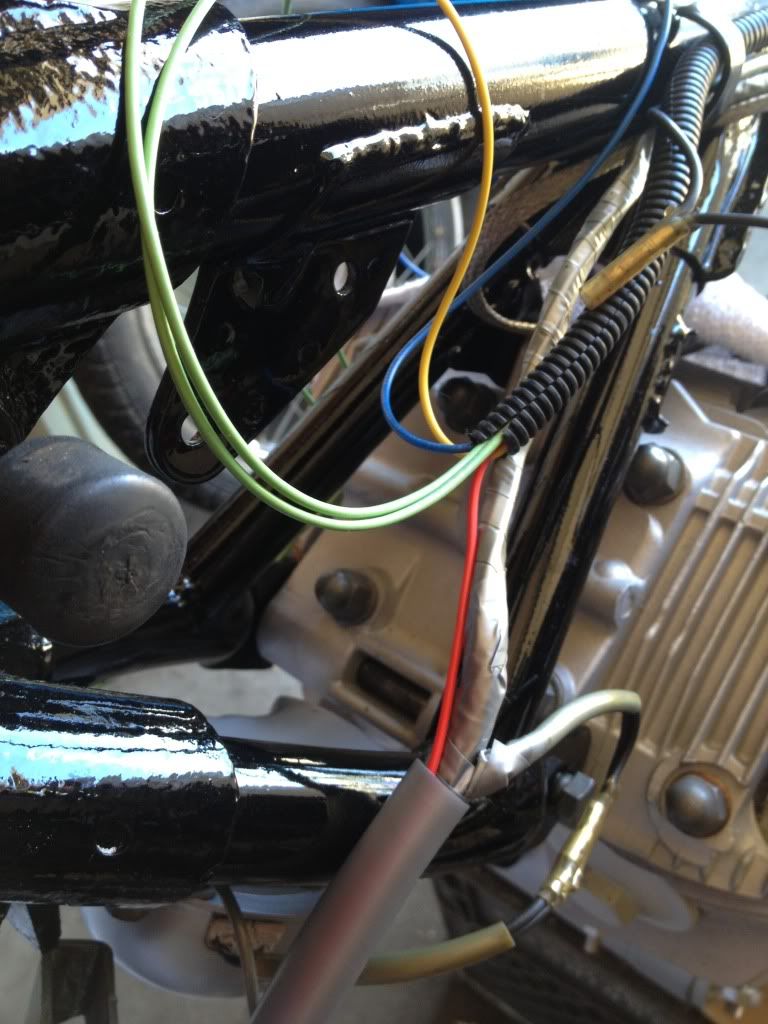
The second shot shows the wiring from the controller to the coils. Yellow is for the left coil, blue is for the right. The green wires are ground, they'll be earthed to the same bolt that the ground strap from the engine to the frame is attached to. You can see how I fed the red wire through the sheathing to the headlight shell for 12V power - it will plug into the black wire in the headlight shell.

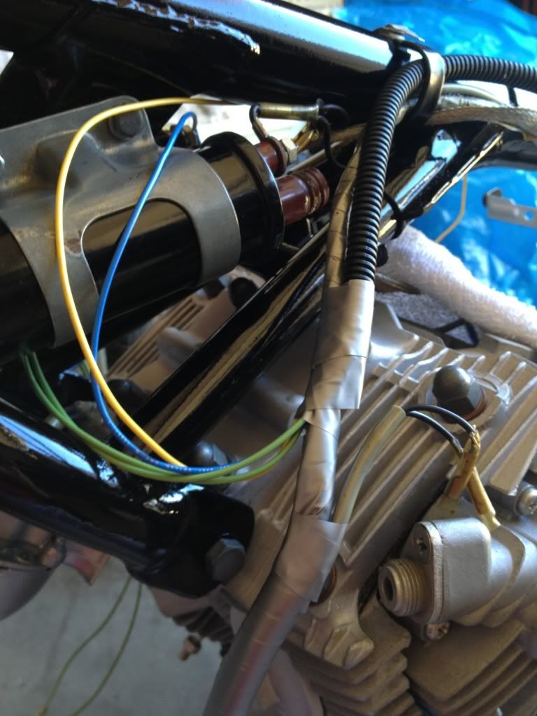
The third photo shows the whole deal all buttoned up. I'll trim the wires and get them attached to their respective terminals and mounts when I get the coils mounted, which will be after I find a hose for that breather pipe. And, when I am assured the controller will work where I want to mount it! I haven't checked the fuel tank for that wire bundle clearance yet, but I'm reasonably sure there is enough room for it.

Image

Image

Image