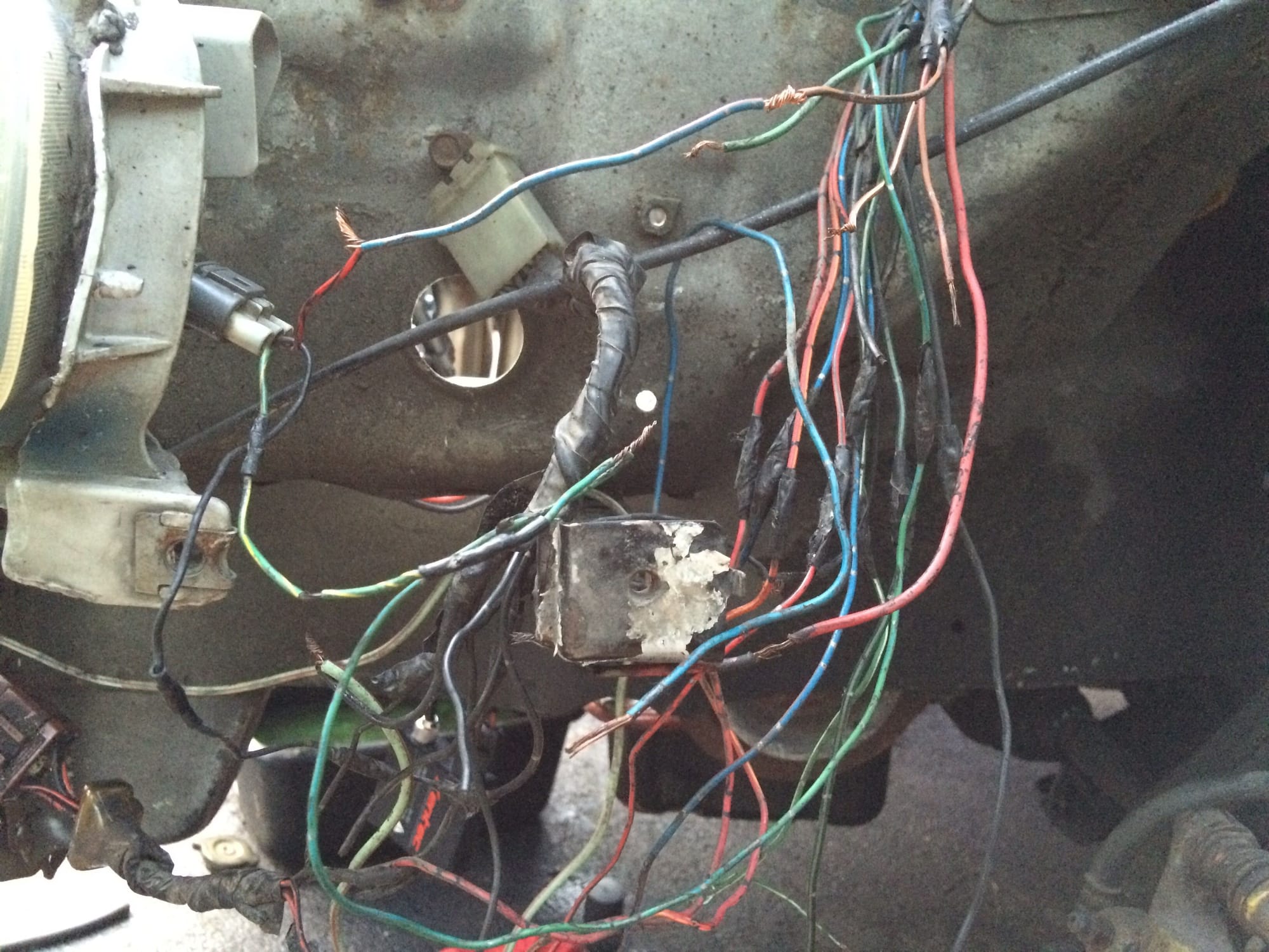
I recently purchased a 95 integra with a jdm front. All of the lights work almost properly except for the turn signals. The back ones work fine, but nothing from the fronts, so obviously someone in the past botched the wiring. I also believe they used the usdm turn signals (I think) because they are 3-wire bulb sockets. I have no idea why the wiring is so janky if this is the case.
So, I took a look today, and I found that it is a huge mess and can't figure it out myself. I've been poking around with a test light and trying to find a guide or wiring diagram that covers what I need but haven't succeeded. When I first began, the grn/yel wire on the pigtails were wired to the grn/yel wire on the passenger side and the grn/blue wire on the driver side. This seems correct seeing as both of these wires receive a pulsing voltage when the blinkers or hazards are turned on. The black wires on the pig tails are both wired to one of the random black wires that goes to the white connector bolted inside the fender wells (ground?). The red wires, however were both spliced into wires that when disconnected, receive no voltage under any circumstances.
Here are some additional notes that I took while I was playing with the test light that may potentially be relevant. All of these are assuming the turn signal pigtails are not connected at all:
Passenger side:
Green/yellow pulses with hazards and blinker
One of the white wires always has power
Green/red always has power
Blue/red has power with ignition on only
Driver side:
Green/blue pulses with hazards and blinker
Brown/black has ignition power only
Green barely lights test light with ignition on
Other, but potentially relevant, notes:
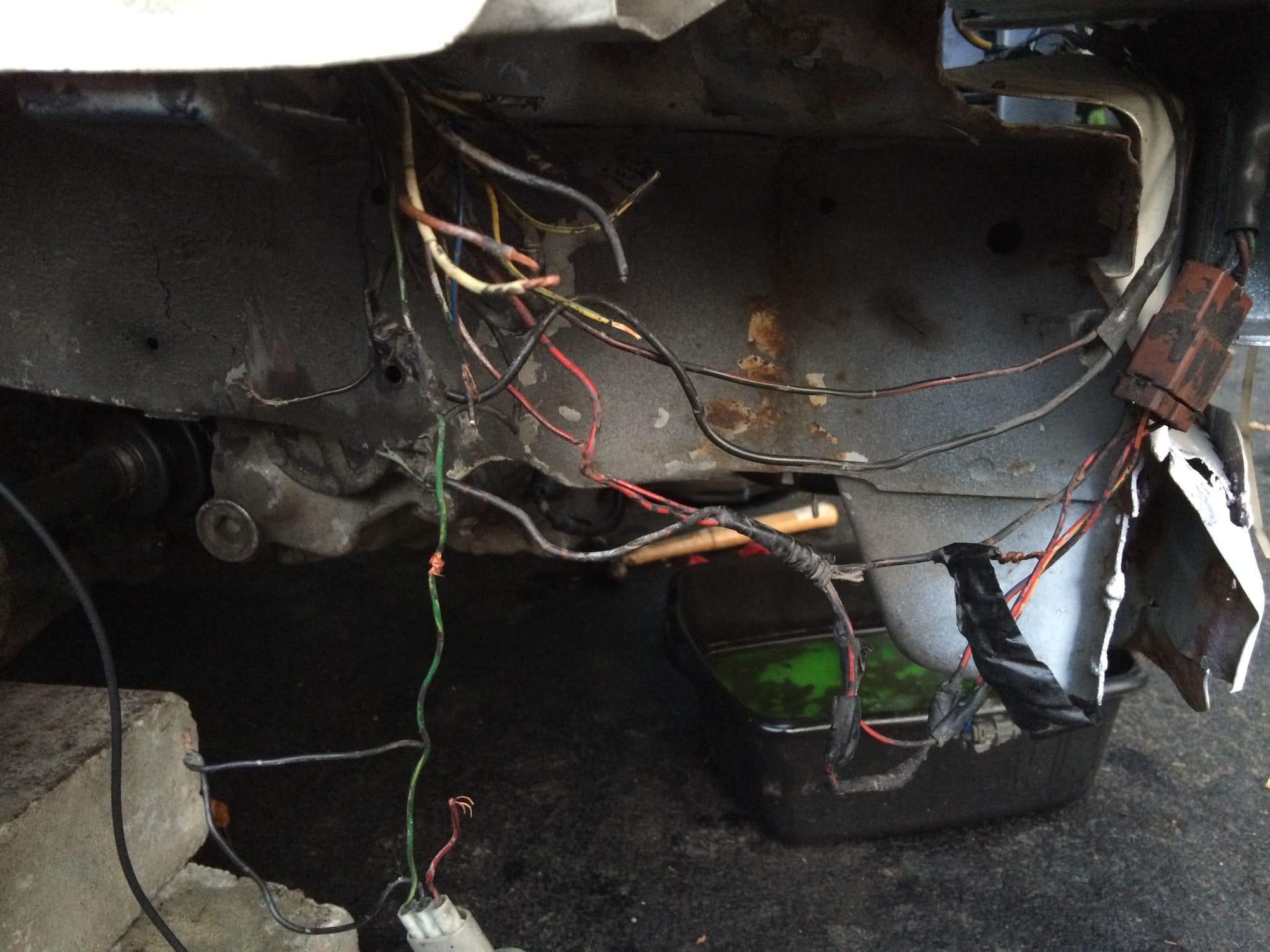
Light switch08 to parking lights:
Driver side: nothing but city lights
Passenger side: city lights, parking lights, and low beams(?)
Light switch to lights on:
Low beams, parking lights, city lights all on
I am at a bit of a stonewall here and I can't even find a suitable wiring diagram let alone figure out everything that was screwed up by a previous owner. Any help would be greatly appreciated!
UPDATE: With the driver side turn signal wired to the green/blue wire (one that gets pulsing turn signal voltage) and one of the black wires that goes into the white fender well connector that I mentioned previously, leaving the red wire completely disconnected, the driver side turn signal functions properly. When I wire it the same way on the passenger side, I get nothing.
The blue between the brown/black and red is just a temporary jumper I put in between that yielded the result I mentioned with the corner light always on